 2026-11-02
SPI NOR FLASH / REPLACEMENT AND TROUBLESHOOTING
If an SPI flash replacement is not working, identify the first failed stage: compatibility, detection, data reading or boot. A device that fits the board may still be incompatible. A valid JEDEC ID confirms an identification response, but does not prove that firmware reads or system startup will succeed. Record the original and replacement part numbers before changing the hardware again.
This guide covers SPI NOR flash used for firmware, boot code and configuration storage. It organizes the checks needed after a replacement fails, with links to detailed guides where a specific investigation is required. SPI NAND, eMMC and parallel NOR need their own device-specific procedures.
Where does the replacement stop working?
Replace the general report “the new chip does not work” with an observation that can be reproduced. Record the actual response, the tool used and the conditions. A programmer result and a board result are different tests.
| Observation | Next investigation | Do not conclude yet |
|---|---|---|
| Voltage or pin compatibility is unknown | Compare full ordering codes, datasheets and the board schematic. | Matching capacity means the part is suitable. |
| No valid JEDEC ID | Check power, connections, command framing and interface state. | The chip must be defective. |
| Valid ID, incorrect data | Check the read operation, address and expected contents. | Identification proves memory access works. |
| Programmer verifies; board will not boot | Compare the programmer operation with the board’s startup sequence. | The two environments use identical settings. |
| Cold boot and warm reset differ | Capture startup conditions and device state in both cases. | One successful restart qualifies the replacement. |
| Failure occurs only at higher speed | Compare timing and signal quality at passing and failing settings. | The replacement is unusable at every speed. |
- 1. CompatibilityCan this device operate on the board?
- 2. DetectionDoes identification work reliably?
- 3. ReadingAre the expected bytes returned?
- 4. BootDoes the system start and operate?
1. Record what changed before testing again
Keep the original and replacement ordering codes together, including suffixes. Also record the board revision, firmware version, programming method and any configuration changes. A comparison becomes difficult to interpret if the chip, firmware and wiring all change between tests.
Establish whether the original board worked before rework. When practical, compare with a known-good board using the same software and test setup. If the original device also fails after reinstallation, investigate the board, connections and rework before assigning the fault to the substitute.
Use our SPI flash replacement compatibility checklist when the candidate has not yet been fully compared with the original. That guide addresses whether a replacement is suitable; the steps below address where an attempted replacement fails.
2. Confirm voltage, package and pin compatibility
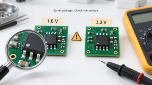
Check the operating supply range and signal-level requirements of the exact variant. Compare the package drawing and every connected pin function. A matching number of pins does not establish the same footprint or the same use of auxiliary pins.
For example, a hypothetical 1.8 V candidate is not a direct substitute for a 3.3 V-class part on an unchanged supply. Read our SPI flash voltage compatibility guide before attempting a voltage-domain change.
Measure the supply at the fitted device during the failed operation, not only at the regulator. Inspect orientation and solder connections with power removed. For a programmer or adapter, confirm both its supply and signal settings against the flash requirements.
Stop when a mismatch is identified. More software experiments will not resolve an incompatible supply or incorrect pin connection. Document the mismatch and decide whether the board can be changed or an exact compatible part is required.
3. Separate detection failure from data-read failure
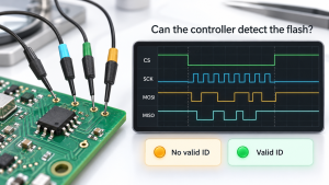
If identification fails, save the received bytes and repeat the transaction under the same conditions. An all-FF, all-00 or unstable response is a starting observation, not a complete diagnosis. Follow the JEDEC ID troubleshooting guide for the detailed communication checks.
If a repeatable ID matches the fitted device but software rejects it, inspect software support. The Linux SPI NOR framework documentation explains that SFDP data can describe device capabilities, while some parts still require explicit support or corrections. Recognition depends on the software and device, not just the advertised capacity.
When the ID is correct but the data is wrong
Choose a region whose expected contents are known. Record the command, address, length and read settings, then compare repeated reads. If the results change between identical attempts, establish reliable communication before analyzing a firmware image.
For stable but incorrect data, verify that the intended image was programmed at the intended location. Compare supported read commands, address handling, bus width and required latency with the exact device documentation. Preserve existing data before any authorized erase or programming test.
4. If the programmer succeeds but the board will not boot
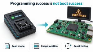
A programmer can use an access method that differs from the board’s boot sequence. Its successful verification is useful evidence, but does not demonstrate that the board issues compatible commands from reset.
Start with the host processor’s boot documentation and the replacement flash datasheet. Identify the earliest operation the board attempts and compare it with a capture. Do not assume that a later application driver can repair a failure occurring before that application loads.
| Check | Question | Evidence to collect |
|---|---|---|
| Initial interface state | Do the host and flash start in compatible modes? | Startup settings and the first command capture. |
| Read configuration | Are opcode, bus width and latency appropriate? | Host configuration compared with the flash command table. |
| Image location | Are the required bytes stored where the boot process expects them? | Programming record and image comparison. |
| Reset behavior | Does the fault depend on a full power cycle or host-only reset? | Separate cold-start and warm-reset records. |
| Startup timing | Is the flash ready when the first access occurs? | Supply, reset and chip-select timing capture. |
One documented example is a command-width mismatch. Infineon’s guidance on legacy SPI commands in QPI mode explains why the covered devices will not accept a one-line command while configured for QPI command input. Use the recovery method for the exact part; do not send guessed mode-switching commands.
A practical comparison, not a universal fix
Suppose a programmer reads an image consistently, but the installed board fails immediately after reset. Keep the verified image and programming record. Next compare the board’s first transaction with the documented startup requirements. This narrows the investigation without assuming that another replacement chip will solve it.
5. Check the level shifter only if the board uses one
Some flash connections are direct; others cross voltage domains through a translator. Follow the schematic before adding this branch to the investigation. Where a translator exists, compare signals on both sides rather than only at the host.
Check its supplies, enable state, signal direction requirements and loading. For example, the TI TXS0108E datasheet defines supply constraints, OE behavior and load-dependent operating conditions. The interface name alone does not establish that a translator suits the assembled circuit.
Our TXS0108E vs TXB0108 selection guide provides a separate comparison when either family is being considered. These devices are not mandatory additions to an SPI flash circuit and should not be proposed as a generic repair.
6. Validate more than a single successful boot
Once the immediate fault is resolved, record the conditions under which the replacement works. Set validation requirements from the product’s actual use, rather than declaring approval after one successful transaction.
- Repeat the relevant cold-start and reset sequences.
- Verify the required image regions and normal operating reads.
- Check firmware-update, erase and programming behavior where the product uses them, using authorized test data.
- Test the supply, temperature and operating conditions required by the product specification.
- Record any firmware or hardware changes needed by the replacement.
The Linux documentation separately covers identification, erase, programming and read verification. That separation is useful: passing one operation should not silently stand in for testing the others.
7. Turn the findings into a clear sourcing request
Engineering findings should change the purchasing request. If no board or firmware changes are permitted, state that constraint. If a candidate works only after modifications, describe those changes and its approval status instead of calling it an unconditional drop-in replacement.
The SPI NOR flash sourcing guide covers broader purchasing checks. For a replacement enquiry, include the details that distinguish an exact-match order from an alternative evaluation:
Original manufacturer and complete part number:
Proposed replacement, if any:
Required quantity and delivery date:
Required package and voltage:
Hardware changes permitted: Yes / No
Firmware changes permitted: Yes / No
Required part: Exact match / Candidate for evaluation
Engineering approval status:
Need the original part or a replacement quotation?
Send EASYIEE the complete original ordering code and your sourcing requirements. List any candidate replacement separately so the quotation distinguishes the requested part from an alternative awaiting validation.
Frequently asked questions
Can two SPI flash chips with the same capacity behave differently?
Yes. Capacity alone does not establish matching electrical requirements, pin functions, commands or startup behavior. Compare the exact devices and the host’s requirements.
Does a correct JEDEC ID prove the replacement will boot?
No. It confirms a valid identification response under the tested conditions. Data access and the board’s boot process still need to be checked.
Should I buy another chip if the first replacement fails?
First record where the process fails. Otherwise, a second part may encounter the same unresolved board or software condition.
This guide organizes replacement investigations using the linked technical references and related EASYIEE guides. Examples describe diagnostic reasoning, not laboratory results or a certified replacement list. Final compatibility and production approval require evidence for the exact hardware and firmware.