 2026-10-22
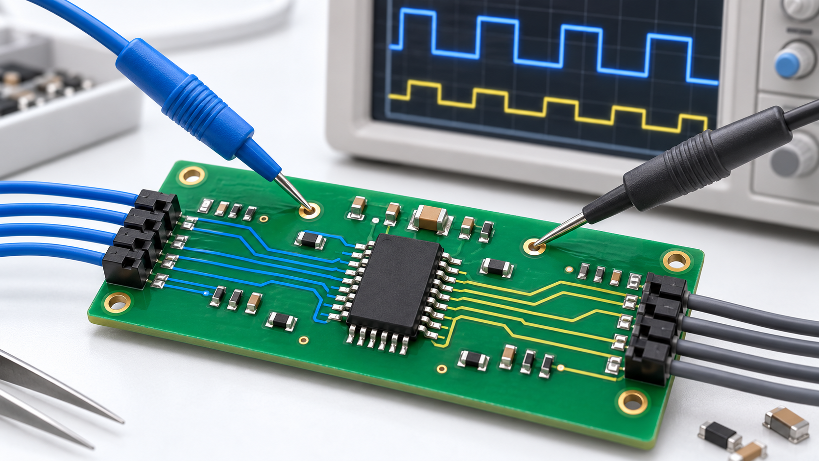
A circuit board can contain hundreds of parts, but most belong to a manageable set of component families. Learning those families makes a board easier to understand: resistors set currents and voltages, capacitors store charge, transistors control signals, and integrated circuits perform more complex tasks.
What are electronic components? Electronic components are individual devices used to build electronic circuits. Common examples include resistors, capacitors, inductors, diodes, transistors, integrated circuits, optocouplers, sensors, relays, switches and connectors. Their electrical specifications and connections determine what they do in a particular circuit.
Recognizing a component family is the first step. Identifying an exact replacement requires its part number, package, pinout and ratings, not just a similar appearance.
A practical list of electronic components
The table below connects common component names with their jobs and typical PCB reference designators. These board labels are conventions, not universal rules. The schematic and bill of materials remain the best references for a specific assembly.
| Component | Main function | Common board label | Important checks |
|---|---|---|---|
| Resistor | Limits current, divides voltage or sets bias | R | Resistance, tolerance, power and voltage rating |
| Capacitor | Stores charge; supports filtering, timing and decoupling | C | Capacitance, voltage, dielectric, ESR and polarity |
| Inductor | Stores magnetic energy; supports conversion and filtering | L | Inductance, saturation current, RMS current and resistance |
| Diode | Rectifies, clamps, protects or emits light, depending on type | D; sometimes LED for indicators | Diode type, polarity, voltage, current and switching behavior |
| Bipolar transistor | Amplifies signals or switches current | Q | NPN/PNP type, pinout, voltage, current and thermal limits |
| MOSFET | Controls current using gate-to-source voltage | Q | Channel type, gate drive, on-resistance and thermal limits |
| Integrated circuit | Performs logic, processing, memory, analog or power functions | U or IC | Exact model, supply, package, pinout and interface |
| Optocoupler | Transfers a signal optically across an isolation barrier | U, IC or a project-specific label | Output type, isolation, speed and CTR where applicable |
| Sensor | Converts a physical quantity into an electrical response | Varies | Measurement range, accuracy, supply and output type |
| Relay | Controls switching using an electrical input | K or RL | Input or coil requirements, contact arrangement and load rating |
| Switch | Opens, closes or selects circuit connections | SW or S | Contact arrangement, operating action and electrical rating |
| Connector | Provides a separable electrical connection | J, P or CN | Pitch, pin count, mating part, keying and current rating |
What the different component types actually do
Resistors, capacitors and inductors: controlling current and stored energy
A resistor can limit LED current, form a voltage divider or help set an amplifier’s gain. It is not selected by resistance alone: a small chip resistor and a larger power resistor can have the same resistance but very different dissipation limits. Browse the resistor category when you have established the required value, package and ratings.
Capacitors store charge and appear throughout a board. Small ceramic capacitors near IC supply pins commonly support decoupling, while larger capacitors may help smooth a power rail. A polarized capacitor must be connected correctly. Nominal capacitance also does not describe every operating condition: temperature, frequency and applied voltage can affect performance, depending on the technology.
Inductors store energy in a magnetic field. In a switching converter, an inductor works with switching devices and capacitors to transfer energy. In a filter, it helps shape the frequency response. An inductor that fits the footprint can still be unsuitable if its saturation or thermal current rating is too low.
Diodes, bipolar transistors and MOSFETs: directing and controlling current
A rectifier diode conducts primarily in one direction within its intended operating limits. Other diode families serve different purposes: TVS diodes suppress transients, Zener diodes operate in controlled reverse breakdown, and LEDs emit light. They are not interchangeable simply because all are called diodes.
Bipolar junction transistors come in NPN and PNP forms and are used for amplification and switching. MOSFETs are another transistor family, commonly used in power conversion and load switching. For a MOSFET, the gate threshold voltage is not a promise of low-resistance operation at that voltage. Check the gate-drive conditions associated with the specified on-resistance.
Small three-pin packages can contain a transistor, diode pair, regulator or another device. Package shape alone cannot establish the component’s function or pin assignment.
Integrated circuits: many circuit elements inside one package
An integrated circuit combines circuit elements on a semiconductor die. The category includes operational amplifiers, logic gates, microcontrollers, voltage regulators, data converters and memory devices. Two eight-pin ICs can perform completely different jobs.
If the terminology is unfamiliar, start with what the IC abbreviation means. To investigate a specific device, use the full ordering code and the manufacturer’s datasheet; the integrated circuit catalog provides product pages to explore after the required function is known.
Optocouplers and sensors: transferring or detecting information
An optocoupler uses light to transfer information between electrically separated circuits. Its output may be a phototransistor, logic output or another structure. A slow phototransistor optocoupler and a gate-driver optocoupler serve different requirements; isolation ratings alone do not make them substitutes. The optocoupler selection guide explains the additional checks.
A sensor responds to a physical quantity such as temperature, pressure, magnetic field or light. Its output might be a changing resistance, an analog signal or digital data. Before selecting the surrounding circuitry, establish the sensor’s measurement range, supply requirements and output format. A connector with the right number of pins does not prove interface compatibility.
Relays, switches and connectors: making the right connection
An electromechanical relay uses a coil to operate contacts. A solid-state relay switches through semiconductor devices instead, so leakage, voltage drop and AC/DC suitability need separate attention. Select by the actual load and switching conditions, not just a headline current rating. The relay category is a starting point for checking individual devices.
A mechanical switch may simply turn a circuit on and off or change several connections together. SPST, SPDT, DPST and DPDT describe contact arrangements, while momentary and maintained describe operating action. Our toggle switch types guide explains these distinctions without treating them as interchangeable specifications.
A connector needs more than a matching pin count. Pitch, orientation, keying, contact plating and the correct mating part can determine whether an assembly works reliably. Current and voltage ratings must also suit the application.
Active, passive and electromechanical: useful groups, not rigid boxes
Resistors, capacitors and inductors are commonly grouped as passive components. Transistors and many ICs are grouped as active devices because they control signals or provide amplification using energy from a supply. Mechanical switches, connectors and electromechanical relays form another useful group.
Classification depends on context. A diode’s treatment can differ between introductory component lists and circuit-theory definitions, while a sensor can contain several technologies. For practical identification, asking “What does this device do?” is more useful than forcing every part into a single active-or-passive category.
How to identify electronic components on a circuit board
Start with the board documentation, not a guess based on color. A reference designator such as R12 or U3 identifies a position in the circuit; it is not the manufacturer’s part number. A schematic symbol represents electrical function, while the PCB footprint describes the physical connection pattern.
- Read the board label. Use it to locate the matching entry in the schematic or BOM, when available.
- Record the package and markings. Note pin count, dimensions, orientation marks and every readable line of text. Photograph the part before removing it.
- Separate the different codes. A top marking may include a shortened device code, date code or lot information rather than a complete ordering code.
- Check the manufacturer’s documentation. Match the marking, package drawing and pinout. Short marking codes are not necessarily unique across manufacturers.
- Confirm the circuit context. Nearby connections help test an identification, but they do not replace a verified datasheet or BOM entry.
SMD means surface-mount device; it does not describe a particular electrical function. Through-hole parts have leads that pass through the board. Both assembly styles can contain resistors, capacitors, semiconductors and other devices. Many small ceramic capacitors have no value marking, making documentation especially important.
For examples of electrical symbols, see Analog Devices’ circuit and symbol reference. Its introduction to electronic components and equipment also provides a practical starting point for learning component behavior and markings.
Before handling a board: Disconnect power and follow the equipment’s service and discharge procedures. Capacitors can retain hazardous energy after power is removed. This identification guide is not a procedure for working on energized mains or high-voltage equipment.
Why a similar-looking component may be the wrong replacement
A matching body size is only one check. A replacement also needs the correct electrical function, pin assignment, supply range, operating ratings and application behavior. Depending on the device, firmware support, switching characteristics, isolation approvals or thermal performance may matter just as much.
For a resistor, compare resistance, tolerance, power and voltage limits. For a capacitor, also consider dielectric, ESR, ripple current and polarity where relevant. For an IC, confirm the complete ordering code, package-specific pinout and functional requirements. Keep a proposed alternative separate from an engineering-approved replacement.
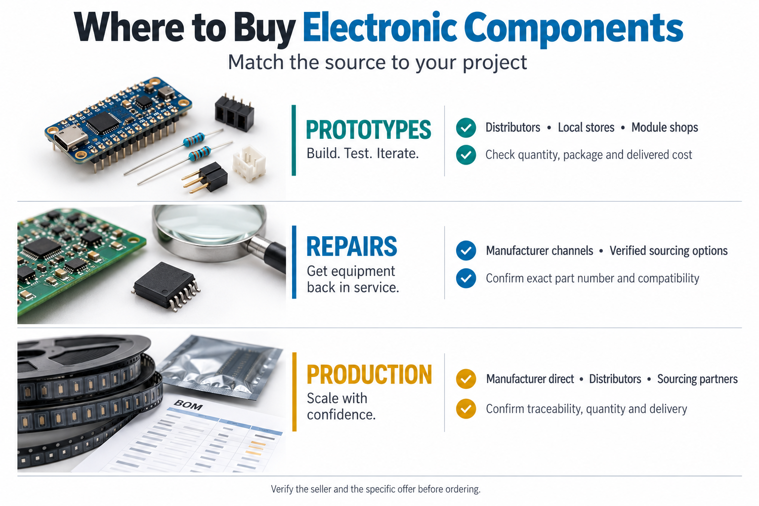
Once the required devices are identified, the BOM sourcing guide explains how to organize those requirements for purchasing. It is a different task from identifying a component family on a board.
Common questions about electronic components
What are the basic electronic components?
A useful starting set is resistors, capacitors, inductors, diodes, transistors and integrated circuits. Practical assemblies also use switches, connectors, sensors, relays and other components according to the circuit’s purpose.
Can I identify a component from a photograph?
A clear photograph can help identify its package and visible marking. It may not reveal the exact device, especially when markings are abbreviated, damaged or absent. Verify the identification against documentation before purchasing or fitting a replacement.
Are all black rectangular components ICs?
No. Diodes, transistors, optocouplers and other devices can also use black molded packages. Color and shape are clues, not reliable proof of electrical function.
Do electronic components with the same value work the same way?
Not necessarily. Two capacitors marked with the same capacitance can differ in voltage rating, dielectric and loss characteristics. Two resistors with equal resistance can differ in power capability, tolerance and temperature coefficient.
Know the component you need?
Browse the electronic component catalog or send EASYIEE your part number or BOM. Include the manufacturer, complete ordering code, quantity and required delivery date. If alternatives are allowed, state that separately so a proposed substitute is not confused with an exact-match request.
For an unidentified part, include clear marking photographs and any available board documentation. Identification, availability, price and delivery require confirmation; a photograph alone may not be enough to establish the correct replacement.
This guide provides general component-identification information. For design, repair and purchasing decisions, use the current manufacturer datasheet, package drawing and application requirements for the exact device.