2022-11-18
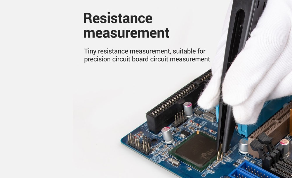
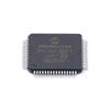
An IC, or Integrated Circuit, is a small chip that contains a very large and complicated circuit. The different circuit components are generated in a semiconductor material with the help of CMOS Technology. ICs can be found in all sorts of electronic devices, from computers to cell phones. An IC can not be repaired and neither it had to be since they come in very cheap cost in comparison to the circuitry they contain. The question often arises in front of us is how to test an ic and when should we throw or replace the IC? In this article, we will discuss four ways to test an IC and if the IC is fine and in proper working condition, it has to pass all four conditions.
The first way to test an IC is by using a Digital Multimeter (DMM). A DMM measures the electrical characteristics of an IC, including voltage and current. It can detect any anomalies in the electrical behavior of the chip that may indicate a problem with the circuits inside. Additionally, a DMM can be used to identify which pins of an IC are connected and how they behave.
The second way to test an IC is with a logic analyzer. A logic analyzer can capture the data output from an IC and analyze it in real-time. This allows engineers to see how the circuit behaves under different conditions, which helps them identify any problems with how the chip works.
The third way to test an IC is with a device called a vector network analyzer (VNA). A VNA can measure how the electrical signals travel through the chip and how they interact with each other. This helps identify any issues in how signals are handled by individual components within the chip, which can prevent it from working properly.
The fourth way to test an IC is with a circuit simulator. This software-based tool can help engineers identify how the different components of an IC interact with each other by running simulations on how the circuits behave under various conditions.
By performing these four tests, engineers can be confident that their integrated circuit is in proper working condition and is ready to be used in an end product. With these tests, they can also pinpoint any issues that may be preventing the IC from working properly and take steps to fix them.
Overall, testing an IC is a necessary step to ensure its proper functioning before it can be put into use. By using Digital Multimeters, Logic Analyzers, Vector Network Analyzers, and Circuit Simulators, engineers can make sure that their ICs are in perfect working order before they move forward with the development of a product.
Conclusion: To ensure an integrated circuit is in proper working condition before it is used in a product, there are four tests that should be performed. These include using a Digital Multimeter, a Logic Analyzer, a Vector Network Analyzer and a Circuit Simulator. By performing these tests, engineers can be sure that the IC is functioning properly before it goes into use.
Thank you for reading! We hope this guide has helped you understand how to test an IC and when to throw or replace it.
By using the above information, we have provided a comprehensive guide on how to test an IC and when to throw or replace it. With this knowledge in hand, engineers can be sure that any integrated circuit they use is in proper working condition before it goes into use. We hope this guide has been helpful and thank you for reading!
To test if an IC is working properly, you’ll need to complete the circuit, then use a multimeter.
To test if an IC is working properly, you’ll need to complete the circuit, then use a multimeter.
To do this, connect the chip to a circuit as shown in Figure 1 and 4. Make sure that you have connected all of the pins correctly and none are left unconnected. If there is any confusion about which pin belongs where, check the datasheet for your part or use a multimeter for help. Once you have finished wiring everything up, plug in power and see what happens! If your circuit has no problems and works properly when powered on (if it shows some kind of output), then congratulations: Your IC is good! However, if your circuit does not work properly when powered on (if no output is observed), then unfortunately we cannot consider this IC “good”.
Place the IC in your circuit as it would be used.
- Place the IC in your circuit as it would be used. You’ll want to make sure that you connect any power sources to the right pins, and that you connect inputs/outputs to their correct pins as well.
- Check the datasheet for the IC to see what pins are connected to what. You may also find it useful to check the circuit diagram for the IC, which will show how it is wired up. If there is no schematic or datasheet available online (which is often true of older chips), then take a look at its schematics elsewhere in your project—you can usually find them in other places around your board as well.*
Touch the probes of your multimeter to each end of the IC’s legs.
- Touch the probes of your multimeter to each end of the IC’s legs. Be sure to touch it firmly and make sure that you are getting a reading on both ends.
- Use the correct polarity: If there is more than one way to attach this test lead, you must use only one method for testing every chip!
- Use the correct range: You have 10K ohms in your multimeter; use it! There is no need to buy another one just because you have 20K or 50K ohms if those don’t work here either (unless someone else tells me otherwise).
- Use the correct mode: This means using “diode check” if we’re talking about diodes or “resistance” if we’re talking about resistors or capacitors
Read the numbers on the display and write them down.
The next step is to read the numbers on your multimeter display. These should be in ohms and will reflect the resistance across each pin of the chip. Write down these values; they’ll be important later.
The next step is to compare these values against what you expect them to be. If you have not already done so, consult your datasheet and find out what resistance values would indicate a working IC or an open circuit (no connection). You can do this by setting up a table like this:
Compare these numbers to known values for that specific IC online or in any maintenance manuals you have for the device in which you found the chip.
To test an IC, you first need to look up the datasheet for your particular chip. If you don’t have one handy and know where to find it online, check out our article on How To Find A Datasheet Online.
- Determine which pin is being tested by referencing your IC’s pinout diagram in conjunction with the datasheet. The pins listed in the diagram indicate which ones are inputs and outputs as well as whether they are bidirectional or unidirectional (i.e., active high or low). You can also tell from this information whether each input must be pulled low before applying a signal—for example, if all inputs are listed as active high but no pull-downs appear next to any of them then this means that these pins require only positive voltage applied through them in order for them to operate correctly (i.e., no other external components).
Take out the chip, replace with a new one.
This is a simple step, but you’ll need to know how to remove the chip from its circuit. Once you’ve done that, replace it with a new one and test the circuit again. If this doesn’t work, try replacing more chips until all of them have been tested and replaced if necessary.
If you have an IC to test, follow these steps to find out its condition..
If you have an IC to test, follow these steps to find out its condition.
- You’ll need a multimeter. If you are testing the chip alone, make sure it’s mounted in the circuit board so that there won’t be any problems with ground-plane issues (it’s best if there isn’t any metal around the chip).
- If necessary, locate the pinout of your IC (its layout diagram). This is often printed on its body or packaging, but if not it can be found online through manufacturer websites or by searching for “IC pinout” plus your specific part number.
- Measure each pin of your IC with your multimeter while looking at its datasheet’s schematic diagram first—you don’t want to short anything out! The schematic will tell you which pins are inputs and which are outputs; some devices may have multiple input pins grouped together as one group (called a bus). Make sure not to confuse them when connecting them back into their original circuit later on during testing!
Conclusion
It’s important to remember that when testing an IC, you shouldn’t use any power (this includes a battery), as doing so can damage the chip. Also stay clear of electrostatic discharge (ESD) by wearing an anti-static wrist strap or working on a grounded surface. If you have any questions about how to test an IC or other components, please don’t hesitate to contact our customer service team at 1-800-823-0588 Monday through Friday from 8 am until 5 pm PST!