2022-11-24
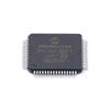
ATMEGA168PA is a microcontroller designed by ATMEL. It has 8 general purpose working registers, 256 byte program memory and 32 byte EEPROM memory. This device has a built-in serial communication interface that allows you to control the microcontroller through a standard RS232 port. This device also supports external crystal oscillator for operating at the same frequency as the internal RC oscillator.
Features of ATMEGA168PA-AU Microcontroller:
The following are the key features of the 66AK2G12ABY60 and ATMEGA168PA microcontroller: – The ATMEGA168PA microcontroller features an 8-channel Dio clock generator for flexible PWM applications. The Dio clock input is selectable from the internal RC oscillator or an external quartz crystal. – Programmable RC oscillator circuitry provides the best possible conversion from 3.3 V to 5.0 V for analog and digital circuits operating from a single 5.0 V power supply. The oscillator is disabled when the microcontroller is operating from a 4.0 V power supply. – The microcontroller features a 32-bit ARM® Cortex™-M3 core and a 512 KB EEPROM memory. The microcontroller integrates a robust peripherals subsystem, including a 12-bit ADCs, digital filters, and a set of six USARTs. – The microcontroller is fabricated with advanced digital-to-analog (D/A) converters that algorithmsically optimize the switching behavior to provide unprecedented dynamic range, linearity, and accuracy. – Two on-board LEDs for debug and user feedback
Working frequency range
The microcontroller can operate over the entire industrial temperature range of -40°C to +85°C. It can also be used in harsh environments such as -25°C to +75°C. The operating frequency is programmed via an internal oscillator circuit. The RC oscillator circuit delivers the required frequency according to the program instructions. The microcontroller has an integrated crystal oscillator circuit that provides an internal clock frequency of up to 200 kHz. The frequency is programmable from 8.0 KHz to 200.0 KHz. The microcontroller can be programmed to operate in the following frequency ranges: – 8.0 KHz to 16.0 KHz – 16.0 KHz to 25.6 KHz – 26.0 KHz to 37.8 KHz – 38.0 KHz to 50.2 KHz – 50.2 KHz to 62.5 KHz – 62.5 KHz to 125 KHz – 126.0 KHz to 250 KHz
Built-in serial communication interface
The built-in serial communication interface of the ATMEGA168PA provides a clock in, data out, and reset signal to communicate with external devices. The interface is configured as a standard RS232 interface. The serial communication port can be used to control devices such as sensors and LEDs through a standard controller. You can connect the microcontroller to external devices such as computers, industrial control systems, or other microcontrollers for communication. The built-in serial communication interface can also be used for programming the microcontroller. You can connect the microcontroller to a programming device such as a programmer, programmer cable, or an in-circuit programmer (ICP). The microcontroller has a built-in LED that blinks when data is being transmitted over the serial communication interface.
Two on-board LEDs for debug and user feedback
The microcontroller has two LEDs for debug and user feedback. The debug LED is used to debug the code. The user LED is used to inform the programmer or user. The LEDs turn on when a logical HIGH level is applied to the corresponding pins. The LEDs indicate the logical state of the pins. The following are the locations of the LEDs: – The debug LED is on-board on P9_13, P9_14, P9-16, P9-17 and P9-18. – The user LED is on-board on P9-15.
Reset and Power supply pin options:ATMEGA168PA-AU
The microcontroller has a built-in reset input pin. The microcontroller also has two power supply pin options. The microcontroller has a 3.3 V power supply pin and a 5 V power supply pin. The 3.3 V power supply pin option can be configured as a shutdown input pin or configured as an input for programming. The following are the details of the reset and power supply pin options: – The reset pin is on-board on P9_4 and P9-7. – The microcontroller has a built-in 5.0 V power supply pin. – The microcontroller has an on-board 3.3 V power supply pin.
Pin assignment and usage guidelines
The following table shows the pin assignment and usage guidelines of the ATmega168PA microcontroller: – The microcontroller has eight general purpose working registers. These registers can store a single 32-bit integer value. The working registers are R0 to R7. – Each working register has an associated read/write control for accessing the register. The control is shown in the table. – The microcontroller has an 8-bit Program Pointer. This value can be accessed from the program memory or from the working registers. – The microcontroller has a 32-bit EEProm Data Pointer. This address is accessible to the program memory address or the EEProm address. – The microcontroller has a 32-bit EEProm Control Pointer. This address is accessible to the program memory address or the EEProm address. – The microcontroller has a 16-bit Stack Pointer. This value is accessible to the program memory address or the EEProm address. – The microcontroller has a 32-bit Program Counter. This address can be accessed from the program memory address or the working registers. – The microcontroller has a 32-timestamped Hardware Watchdog Timer. This timer can be configured as a periodic timer or as a single pulse timer.
Conclusion:ATMEGA168PA-AU
The ATMEGA168PA microcontroller is designed for applications that require a high performance microcontroller with an on-chip oscillator. The microcontroller features a Cortex-M3 core, 256 KB of on-chip Flash memory, a 128-bit security key, 32-bit dynamic memory, and a TCxO power supply circuit.